Cable sizing and protection for drive fed motors
The cable between a drive and a motor is not an ordinary power cable carrying ordinary current. It carries a pulse width modulated waveform with extremely fast voltage transitions, and it behaves less like a simple conductor and more like a transmission line. Treating it as though it were the same as a cable from a contactor is the origin of a long list of faults that look like motor problems and are not.
Why the drive output is different
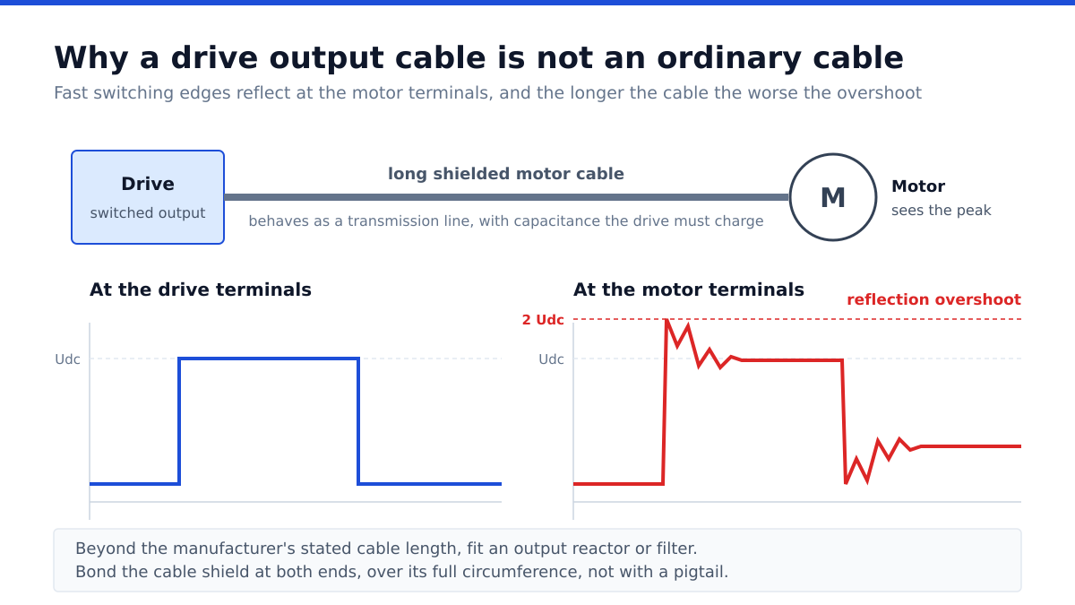
A drive synthesises its output by switching the direct current link voltage on and off thousands of times per second. Each transition has a very short rise time, and a steep voltage step travelling along a cable behaves as a wave. When it reaches the motor terminals, where the impedance of the cable meets the much higher impedance of the motor windings, part of that wave reflects back.
The reflection superimposes on the incoming wave and can produce a voltage at the motor terminals substantially higher than the drive output, in the worst case approaching twice the direct current link voltage. Longer cables make this worse, because the travelling wave has time to develop fully before the next transition arrives.
Two consequences follow. The motor insulation sees repeated overvoltage stress, which ages it, and the first turns of the winding see the steepest part of the step. Motors intended for drive duty are built with inverter rated insulation systems for exactly this reason, and an older motor retrofitted onto a drive may not be.
Charging current and why it loads the drive
Cable capacitance between conductors and to earth must be charged and discharged at every switching transition. That charging current flows from the drive and does no useful work at the motor. On long runs it can become a significant fraction of the drive’s output capability, and the drive may report overcurrent while the motor is lightly loaded, which looks inexplicable until the cable is considered.
Manufacturers publish maximum cable lengths for each drive, often with separate figures for shielded and unshielded cable, because shielded cable has higher capacitance. Beyond those lengths, an output reactor or a filter is required. The reactor slows the rate of voltage rise, reducing both the reflection and the charging current, at the cost of a small voltage drop.
Shielding, earthing and bearing currents
Drive output cables should be shielded, and the shield should be bonded at both ends with a low impedance connection over its full circumference rather than a thin pigtail wire. The reason is that the shield provides a deliberate low impedance return path for the high frequency current that would otherwise find its way back through the building structure, bearings and signal cables.
That stray return path is the mechanism behind bearing damage. Common mode voltage on the motor terminals drives a small current through the bearing, and where it discharges through the lubricant film it causes microscopic pitting that progresses to fluting and eventual failure. On larger machines the remedies include insulated bearings, a shaft grounding ring, output filters and above all proper high frequency bonding of the cable shield and the motor frame.
A symmetrical cable construction, with three conductors and a concentric shield, keeps the magnetic fields balanced and reduces common mode current compared with an asymmetrical arrangement. It is a detail that costs little at installation and is impossible to correct later without pulling new cable.
Sizing the conductors
Current carrying capacity is determined as for any installation, from the motor full load current with corrections for ambient temperature, grouping and installation method. Two adjustments specific to drive circuits deserve attention.
First, harmonic content in the output waveform produces additional heating beyond what the fundamental current alone suggests, so there is an argument for modest additional margin. Second, voltage drop at low speed matters more than it appears, because a motor at reduced frequency has reduced voltage and the same drop represents a larger proportion of it.
Never run motor cables from different drives in the same conduit or bundled together, because each one couples its switching noise into the other, and never run drive output cables parallel to control or analogue signal cables, for reasons set out in our note on PLC panel design, from signal count to wiring discipline.
Protection, and what the drive does and does not do
A drive provides electronic overload protection for the motor, generally based on a thermal model of the current it is supplying, and this normally replaces a separate thermal overload relay. What the drive cannot do is protect the cable between itself and the supply, or clear a short circuit upstream of its own terminals. Short circuit protection on the input side remains necessary and is selected according to the drive manufacturer’s requirements, which often specify particular fuse types.
Earth fault behaviour deserves specific thought. Residual current devices intended for sinusoidal supplies can misoperate on the high frequency leakage current a drive circuit produces, and where earth fault protection is required on a drive circuit, a type appropriate to the waveform must be chosen.
Finally, a contactor should never be opened on the drive output while the drive is running, because interrupting current to an inductive load can destroy the output stage. Where isolation between drive and motor is needed for maintenance, the sequence must stop the drive first, and auxiliary contacts should enforce it.
Related selection considerations are covered in our note on how to size a variable frequency drive for a motor. General background is summarised in the overview of variable frequency drives.
Frequently asked questions
Why does cable length matter on a drive output?
Because fast switching transitions reflect at the motor terminals, raising voltage stress, and cable capacitance draws charging current from the drive. Both effects worsen with length.
Should the cable shield be earthed at one end or both?
Both ends, with a full circumference low impedance bond. This differs from analogue signal cable practice, where one end is usual, because the purpose here is a high frequency return path.
What causes bearing damage on drive fed motors?
Common mode voltage drives small currents through the bearing that discharge through the lubricant film and pit the raceway. Proper shield bonding, insulated bearings, grounding rings or filters address it.
Does the drive replace the motor overload relay?
Generally yes, since the drive provides electronic overload protection. It does not replace short circuit protection on its own input, which remains necessary.
Can I switch a contactor between drive and motor?
Not while the drive is running. Interrupting current to an inductive load can damage the output stage. The drive must be stopped first, and the interlock should enforce it.