Harmonics from variable frequency drives and how filters help
A variable frequency drive is a rectifier followed by an inverter, and the rectifier is the part that causes trouble upstream. It does not draw a smooth sinusoidal current from the supply. It draws current in pulses, and that distorted current flowing through the impedance of the supply distorts the voltage waveform for everything else connected to it. On one small drive this is invisible. On a plant where drives represent a large share of the connected load, it becomes a problem that announces itself through equipment nobody suspected.
Where the distortion comes from
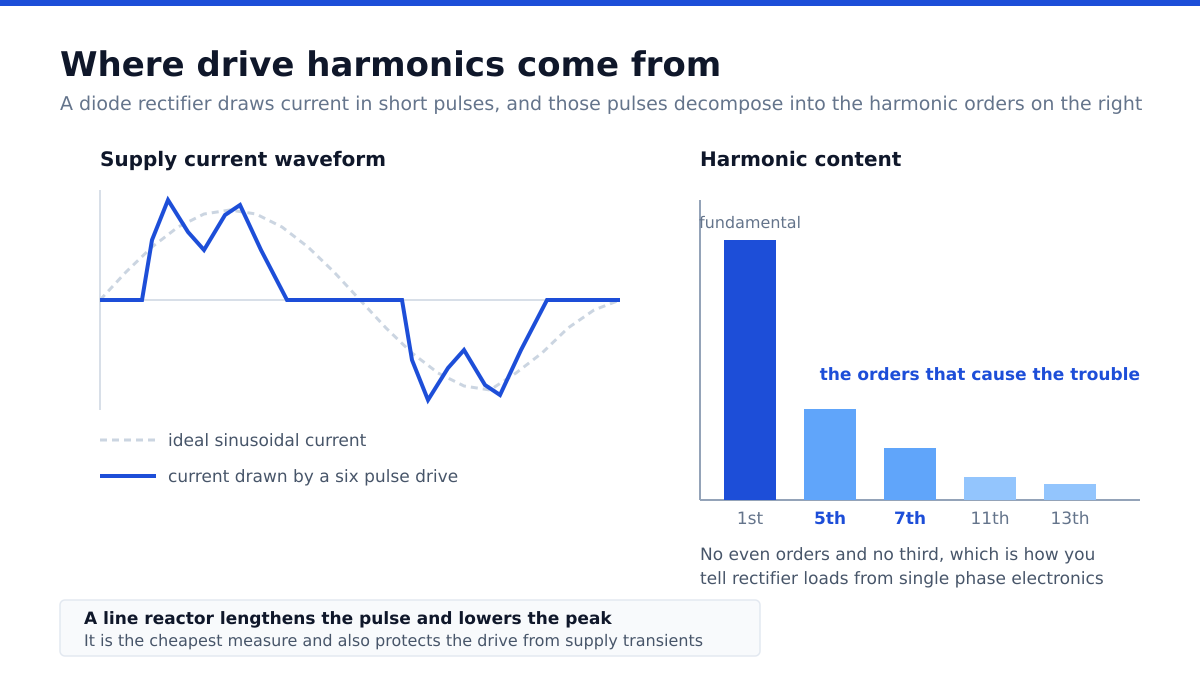
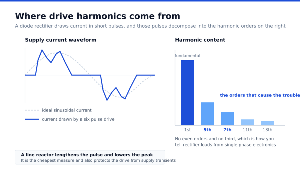
The standard drive front end is a six pulse diode bridge charging a capacitor bank. Diodes conduct only while the incoming voltage exceeds the capacitor voltage, so current flows in two short bursts per cycle rather than continuously. The resulting current waveform, decomposed into its harmonic components, contains strong fifth and seventh harmonics, with eleventh and thirteenth following, and nothing at the even orders or at the third and its multiples.
The useful consequence of that pattern is diagnostic. If a measurement shows a large fifth harmonic in the current, rectifier loads are responsible. If it shows a large third harmonic, the source is single phase electronics such as lighting drivers and computer supplies, not the drives.
Why it matters in practice
Harmonic current causes extra heating everywhere it flows. Transformers run hotter than their nameplate suggests, because iron and eddy current losses rise with frequency, which is why transformers feeding substantial drive load are specified with a derating factor. Cables carrying harmonic current heat more than the fundamental alone would suggest, and the neutral conductor in some configurations carries current that cancellation would otherwise have removed.
Power factor correction capacitors are the most vulnerable component. Capacitive reactance falls with frequency, so a capacitor bank presents a low impedance path to harmonic current and can heat severely. Worse, the capacitance together with the supply inductance forms a resonant circuit, and if that resonance lands near a harmonic the drives are producing, the current can be amplified rather than absorbed. Capacitor failures in a plant that has recently added drives are a textbook symptom.
Distorted voltage also affects motors fed directly from the supply, producing additional losses and torque pulsation, and it can disturb sensitive electronics and measurement equipment.
The remedies, from cheapest upward
Line reactors
A reactor in series with the drive input adds impedance, which lengthens the conduction period and reduces the peak of the current pulse. This is the simplest and least expensive measure, and it typically brings a meaningful reduction in current distortion. It also protects the drive from voltage transients on the supply, which is reason enough to fit one on many installations. The cost is a small voltage drop and some additional losses.
Passive filters
A tuned passive filter presents a low impedance path at a chosen harmonic order, usually the fifth, diverting that current away from the supply. Passive filters are robust and relatively economical, and they work best where the load is reasonably constant. Their drawbacks are that they address only the orders they are tuned for, and that they interact with the supply impedance, so they should be designed against a known network rather than selected from a catalogue.
Multi pulse rectifiers
Feeding a drive through a phase shifting arrangement to produce twelve or eighteen pulse rectification cancels the lower harmonic orders by design. This is an elegant solution for large single drives and requires a dedicated transformer, which makes it a capital decision rather than an accessory.
Active front ends and active filters
An active front end replaces the diode bridge with controlled switching devices that draw near sinusoidal current, which largely eliminates the problem at source and also allows energy to be returned to the supply during braking. An active filter is a separate unit that measures distortion and injects a compensating current, correcting for whatever mix of loads is present at the time. Both are the most effective and the most expensive options, and both suit situations where distortion limits must be met reliably across a varying load.
How to approach it on a real site
Measure before specifying. A power quality survey at the point of common coupling, recording voltage and current distortion across a representative period, tells you whether there is a problem and which orders dominate. Many sites worried about harmonics turn out to be within limits because their drive load is modest relative to the supply capacity.
Calculate the ratio of total drive load to the supply transformer rating, since that ratio is the strongest single predictor of whether distortion will be significant. Check whether power factor correction capacitors are installed, because if they are, resonance must be examined before anything else. And establish what limits actually apply, whether from the utility connection agreement or from internal standards, so that the remedy is sized against a requirement rather than an impression.
Fitting line reactors as standard practice on new drive installations is inexpensive insurance, and it pairs naturally with correct drive selection as described in our note on how to size a variable frequency drive for a motor. Where variable speed is not actually required, avoiding the rectifier altogether is the cleanest answer, which is one of the arguments in our piece on soft starters compared with variable frequency drives. General background is summarised in the overview of harmonics in electrical power.
Frequently asked questions
Do all drives cause harmonic distortion?
Any drive with a diode rectifier front end draws distorted current. Drives with active front ends draw near sinusoidal current and largely avoid the problem.
Why do capacitor banks fail after drives are installed?
Capacitors present low impedance to harmonic current and can overheat, and the capacitance with supply inductance may resonate near a harmonic the drives produce, amplifying it. Resonance should be checked before adding either.
Is a line reactor enough?
Often it is sufficient on its own for moderate drive load, and it also protects the drive from supply transients. Heavy drive load relative to transformer capacity usually needs more.
How do I know which harmonics I have?
Measure. A dominant fifth harmonic points to three phase rectifier loads such as drives. A dominant third points to single phase electronics instead.
Does a soft starter cause harmonics?
Only briefly during the start ramp. Once bypassed it is out of circuit and the motor draws essentially sinusoidal current.