PLC panel design, from signal count to wiring discipline
A programmable logic controller panel is where the control philosophy of a machine stops being a document and becomes copper, terminals and heat. Panels that work for twenty years and panels that cause intermittent faults nobody can trace often contain the same components. The difference is almost always in decisions made before anything was mounted.
Start by counting, then add margin
The first task is a complete input and output list. Every sensor, switch, valve, contactor, drive and indicator that the controller must read or command, with its signal type. Digital inputs from proximity sensors and limit switches. Digital outputs to relays and solenoids. Analogue inputs from pressure and temperature transmitters. Analogue outputs to control valves and drive references. Temperature inputs requiring thermocouple or resistance sensing. Communication connections to drives and instruments.
Count them, then add spare capacity. Something between a fifth and a third of each signal type is a common allowance. This is not padding. Modifications happen, and the cost of a spare channel at build time is trivial compared with adding a module to a full rack in a running plant, which often means a shutdown.
Field devices connected by a fieldbus change the arithmetic considerably, because many drives and instruments can report over a single connection rather than consuming individual channels. Where a plant already has drives, reading their status over the network rather than wiring discrete signals saves both terminals and panel space.
Separating what must not be mixed
The most common cause of baffling intermittent faults in control panels is coupling between power and signal wiring. Switching currents in motor cables and drive outputs generate interference that induces voltage into nearby low level signal conductors. An analogue measurement that drifts whenever a particular motor starts is almost always a routing problem rather than a sensor problem.
Good practice separates the panel into zones. Incoming supply, protective devices and contactors in one area. Drives, which are the noisiest components present, in another with their own routing. Low voltage control and analogue signals in a third, in separate trunking, crossing power routes at right angles rather than running parallel to them. Shields on analogue cables earthed at one end only, consistently, to avoid circulating currents.
Where a drive shares an enclosure with a controller, the drive’s input and output cables should be kept away from signal wiring along their whole length, which in a crowded panel takes deliberate planning rather than good intentions.
Power supply and what happens when it fails
Control circuits usually run from a direct current supply derived from the incoming alternating current. Size it for the total load of controller, modules, sensors and relays with headroom, remembering that some devices draw a brief inrush at switch on that far exceeds their steady consumption.
Think through behaviour on power loss and restoration. Which outputs must fail to a safe state. Whether the controller restarts automatically or requires acknowledgement. Whether retentive memory holds the values it needs to resume sensibly. A machine that restarts in an unexpected state after a brief dip is a safety matter as much as a nuisance.
Safety circuits are not ordinary inputs
Emergency stop, guard interlocks and light curtains belong to a safety function with its own requirements, and wiring them as normal inputs to a standard controller is not acceptable practice. Safety functions are implemented with safety relays or a safety rated controller, with dual channel wiring, monitored contacts and defined reaction, so that a single fault cannot defeat the protection.
This separation also makes the panel easier to understand. Anyone opening it can see which circuits carry safety duty and which do not, and that clarity has value every time the machine is modified.
Heat, the constraint that limits everything
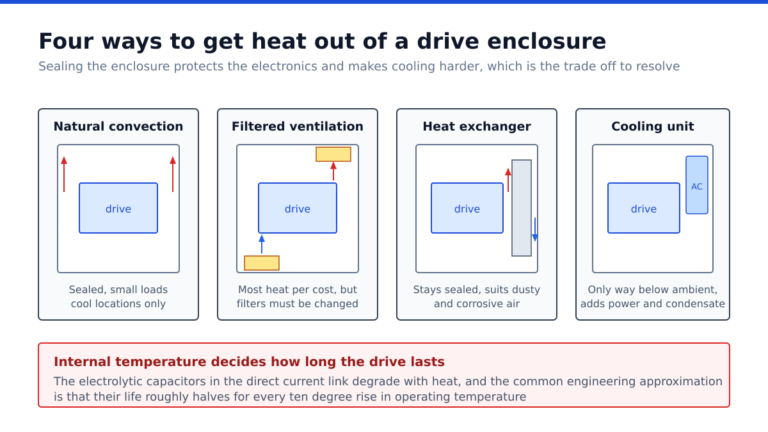
Every component in a sealed enclosure converts some energy into heat, and drives and power supplies convert a lot of it. Internal temperature determines the service life of electrolytic capacitors, and exceeding a device’s rated ambient shortens its life disproportionately.
Panel thermal design means adding up the dissipation of every component, comparing it with the enclosure’s ability to shed heat at the worst case external temperature, and providing filtered ventilation, a fan, a heat exchanger or cooling where the sums require it. Component spacing matters too, because manufacturers specify clearances for a reason and stacking devices tightly to save space defeats their own cooling.
Documentation and the panel’s second life
A panel is built once and maintained for decades, usually by people who were not there when it was built. Every conductor ferruled and matching the drawing. Terminals numbered. A drawing set inside the door that reflects what was actually installed rather than what was first designed. Spare terminals labelled as spare. Input and output assignment lists that match the controller program.
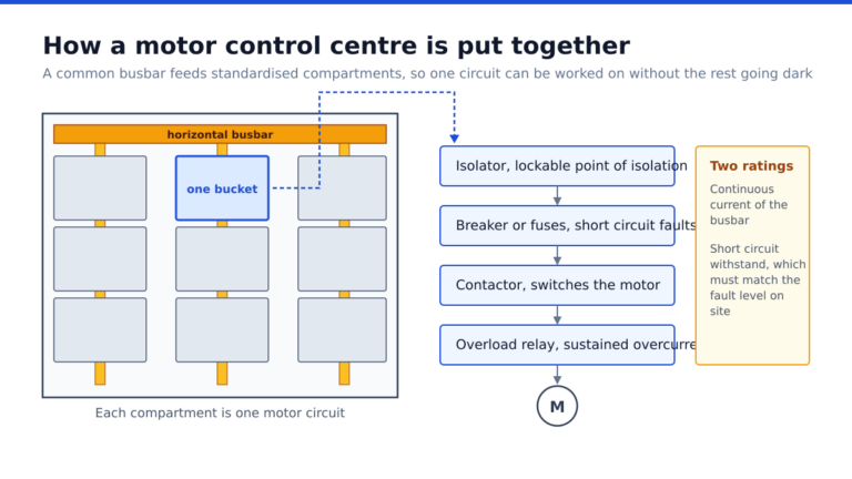
Where drives form part of the installation, their parameter sets should be recorded and backed up, because a replacement drive with factory settings on a commissioned machine is a long evening. The sizing decisions behind those drives are covered in our note on how to size a variable frequency drive for a motor, and the wider assembly they often sit alongside is described in our piece on what goes inside a motor control centre panel. General background on controllers is summarised in the overview of programmable logic controllers.
Frequently asked questions
How much spare input and output capacity should a panel have?
Commonly a fifth to a third of each signal type. Spare channels cost little at build time and a great deal to add once a plant is running.
Why do analogue readings drift when a motor starts?
Almost always because signal cables run alongside power or drive cables. Separate the routes, cross at right angles, and earth cable shields at one end only.
Can emergency stop be wired as a normal controller input?
No. Safety functions require safety rated devices with dual channel monitored wiring, so that a single fault cannot disable the protection.
Does a control panel need cooling?
It depends on total internal dissipation and the worst case external temperature. Calculate the heat load rather than assuming, because internal temperature directly determines component life.
What documentation should be left with the panel?
As built drawings inside the door, ferruled conductors matching those drawings, numbered terminals, an input and output assignment list, and backed up parameter sets for any drives installed.