What goes inside a motor control centre panel
A motor control centre is one of those pieces of equipment that everyone in a plant depends on and few people outside the electrical trade have ever looked inside. It is not simply a cupboard full of contactors. It is an assembly designed so that a dozen or more motor circuits can be protected, switched, monitored and maintained without the whole plant going dark every time one of them needs attention.
The structure of the assembly
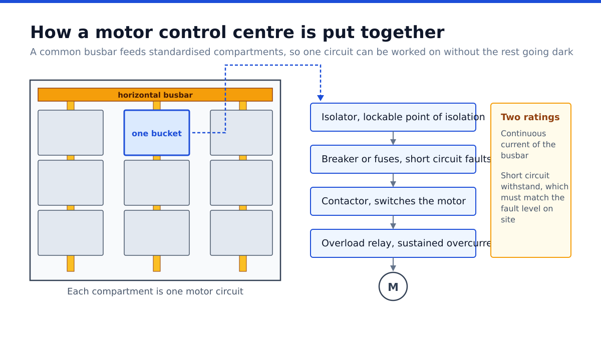
At the top or along the back of the enclosure runs the horizontal busbar, a set of copper or aluminium bars carrying the incoming supply across the full width of the assembly. From it, vertical busbars drop into each column, and from those the individual motor starter units take their supply.
This arrangement is what makes a motor control centre different from a row of separate starters. Because every unit taps the same bus, the assembly can be built as a sequence of standardised compartments, each one removable, each one isolable. A fault in one feeder does not require the busbar to be disturbed.
The bus itself is rated for continuous current and, more importantly, for short circuit withstand. That second rating describes how much fault current the assembly can survive for a specified fraction of a second without the bars deforming or the supports failing. It has to be coordinated with the available fault level at the installation, which comes from the upstream transformer and network.
What a single motor starter unit contains
Each compartment, often called a bucket, holds a complete motor circuit. Working from the supply inwards, it typically contains an isolating device, a short circuit protective device, a switching device and an overload protective device, plus the control and indication that goes with them.
Isolation and short circuit protection
The isolator provides a visible, lockable point at which the circuit can be made safe for work. Short circuit protection is usually a moulded case circuit breaker or a set of fuses, sized to clear a fault quickly without tripping on the normal starting current of the motor. These two functions are sometimes combined in a single withdrawable device.
Switching
A contactor makes and breaks the motor circuit under command from the control system. Contactors are rated by utilisation category, and motor duty is more demanding than resistive duty because of the inductive breaking current. A contactor selected on continuous current alone, without regard to category and to the number of operations expected per hour, wears out early.
Overload protection
Short circuit protection responds to catastrophic faults in milliseconds. It does not protect against a motor drawing modestly excessive current for minutes, which is what happens when a bearing starts to fail or a conveyor jams. That is the job of a thermal overload relay or an electronic motor protection relay, set to the motor’s full load current, which models the heating of the windings and trips before insulation is damaged.
Coordinating these two devices so that each handles the range of faults it is suited to is the central design task, and it is why the devices in a bucket are normally selected as a tested combination rather than individually.
Withdrawable, plug in and fixed construction
Buckets come in three broad forms. Fixed units are bolted in place and must be worked on in situ with the section isolated. Plug in units connect to the vertical bus through a plug arrangement and can be removed with modest effort. Withdrawable units are mounted on a carriage with a defined test position and can be racked out entirely while the rest of the assembly stays live.
Withdrawable construction costs considerably more and earns its price in continuous process plants where taking a whole section out of service to repair one starter is unacceptable. For a workshop with planned shutdowns, fixed construction is often the sensible economy.
Arc flash, forms of separation and safety
Standards define forms of internal separation describing how thoroughly busbars, functional units and terminals are segregated from one another. Higher forms reduce the chance that a fault in one compartment propagates, and they allow work on one unit with less exposure to adjacent live parts.
Arc flash is the hazard that drives much modern design. An internal arcing fault releases enormous energy, and assemblies can be specified as arc resistant, with reinforced construction and vents that direct pressure and hot gases away from the operator. Remote racking, infrared inspection windows and door interlocks all reduce the number of occasions anyone needs to stand in front of an open panel.
Control, monitoring and the modern panel
Older assemblies used hard wired control with relays and pilot lamps. Current practice connects motor protection relays onto a fieldbus, so that current, thermal state, trip history and operating hours are available to the control system without a technician opening a door. This turns the assembly into a diagnostic resource and is the foundation of any serious condition monitoring programme.
Where variable speed is required, a drive may be installed within the assembly or in a separate enclosure, and the thermal consequences of that choice are significant, as discussed in our note on how to size a variable frequency drive for a motor. Where only controlled starting is needed, the choices are compared in our piece on soft starters compared with variable frequency drives. General background is summarised in the overview of motor control centres.
What to establish before specifying one
Record every motor with its full load current, starting method and duty. Establish the available fault level at the point of installation, because that sets the short circuit rating of the assembly. Decide the form of separation and whether arc resistant construction is warranted. Choose fixed, plug in or withdrawable construction on the basis of how the plant is maintained rather than on preference. Confirm the ambient temperature and whether the panel room is ventilated, because enclosure temperature derates everything inside it. And leave spare compartments, because the one certainty about a plant is that somebody will add a motor.
Frequently asked questions
Why are short circuit and overload protection separate?
They address different faults. Short circuit devices clear massive currents in milliseconds. Overload relays detect sustained moderate overcurrent that would overheat the windings over minutes. Neither substitutes for the other.
What does the short circuit withstand rating mean?
It is the fault current the assembly can survive for a specified short duration without mechanical failure of the busbars and supports. It must match or exceed the fault level available at the installation.
Is withdrawable construction worth the extra cost?
In continuous process plants, usually yes, because a starter can be replaced without de energising the section. Where planned shutdowns are routine, fixed construction is often sufficient.
What are forms of separation?
Defined levels of internal segregation between busbars, functional units and terminals. Higher forms limit fault propagation and allow safer work on individual units.
How much spare capacity should be allowed?
Enough compartments and busbar headroom for foreseeable additions. Retrofitting a new section onto an existing assembly is substantially more expensive than specifying spare space at the outset.